Other Items:
1. (2) Yamaha light sockets [5PW-84312-00-00] (Yamaha 03 R1)
Estimates:
Time: 3 - 10 hours
Cost: This varies a great deal, depending on sockets used and if you have most of the material around
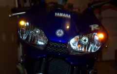
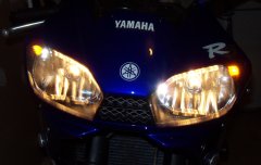
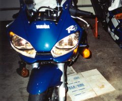
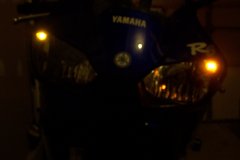
Installing Running Lights in Headlight |
|
| (R6 Specific) | |
| (The running lights will flash alternately with turn signals with this mod) | |
**NEW: Updated parts and pictures have been added for a better setup and visibility!*** There have been updates to the original design. All 5-contacts of the relay are now used. I also reverted back to the stock flasher to resolve a "stuck issue" with the new relays up front. You can also purchase an adjustable one from Libertek.com |
|
| The following directions will show you how to install running lights in the headlight assembly of the Yamaha R6. This will also work for the Yamaha R1 (socket location will be different), and any other bike for that matter. The conversion instructions are meant for (2) single filament sockets, whereas the turn signal would only use 2 wires and the running light would only use 2 wires. | |
| If you want to use dual filament sockets in either or both, or avoid having the running lights blink with the turn signals, make adjustments accordingly. If you need assistance, e-mail suliman@sportbikeguy.com and I'll try to help. | |
|
|
||
| Tools Needed: | 1. Whatever tools that are required to remove the headlight | |
| 2. Wire connector crimper/ stripper | ||
| 3. Rotary tool, such as a "Dremmel" | ||
| 4. Drill | ||
| 5. Set of drill bits from 1/16" to 1/2" | ||
| 6. Awl or punch tool | ||
| 7. Can of compressed air | ||
Other Items: |
1. (2) Yamaha light sockets [5PW-84312-00-00] (Yamaha 03 R1) |
|
| NOTE: If you are having problems getting the Yamaha part from a dealer, please check a auto parts store that sells Blazer products. The Blazer part number you want is C455A. It comes with a socket and a lens, just ditch the lens. The socket is the .5" push in grommet type just like the Yamaha part. | ||
| NOTE: Also, an other option are the following Calterm sockets available at auto parts stores: 08598, 08593, or 08591. One of these should also fit the modification needs. | ||
| NOTE: The Old Yamaha Part [5FL-84312-00] for an R7 is no longer stocked by Yamaha. | ||
| 2. (2) 194NA light bulbs | ||
| NOTE: It is better to use LED than the normal amber bulbs here. The best LED bulb on the market I found was made by JamStrait (www.jamstrait.com). | ||
| 3. (2) Rolls of 18guage wire, one black, one another color | ||
| 4. (2) Trailer wiring kit, 2-pole | ||
| 5. (6) Quick splice connectors [tap-ins] | ||
| 6. (12) In-line connectors [butt connectors] | ||
| 7. (6) Male bullet connectors | ||
| 8. (4) Female bullet connectors | ||
| 9. (2) 5-prong relays | ||
| 10. (2) 5-prong relay harnesses | ||
| 11. Zip ties | ||
| 12. Electrical tape | ||
| 13. Shrink wrap (only if you have a heat gun, not needed, just to clean up connections | ||
| Numbers in (x) represent quantity. | ||
Estimates: |
Time: 3 - 10 hours Cost: This varies a great deal, depending on sockets used and if you have most of the material around |
|
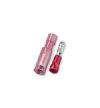
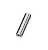
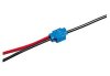
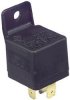
| Here are some pictures of the items if you are not sure about the description: | |||
 |
 |
 |
|
| Bullet | In-Line | Quick-splice | |
 |
  |
 |
|
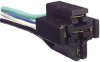
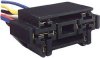
| Relay (330-073) or (330-070) PartsExpress |
Relay Harness (330-075) or (330-078) PartsExpress |
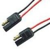
Trailer Harness (270-026) RadioShack |
|
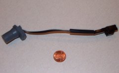   |
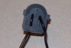
|||
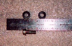
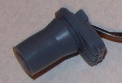
| Yamaha 03 R1 Light Bulb Socket | |||
*I have gotten VERY frustrated with RadioShack and thier part number/ product discontiunuation issues. I have found a source for the relays at PartsExpress.com. |
|||
|
Headlight modifications: |
||||||||||
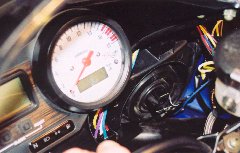
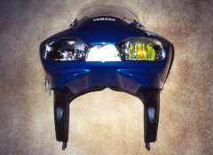
| Step 1 | Remove the headlight from the motorcycle | |||||||||
 |
||||||||||
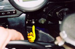
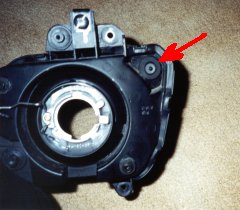
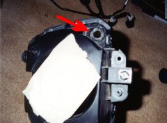
| Step 2 | Locate the location for the running light, you will see dimples where they should be | |||||||||
 |
||||||||||
| Step 3 | Use the rotary tool to smooth the dimple flush | |||||||||
| Step 4 | Use the awl or punch to mark the center of where you will drill | |||||||||
| Step 5 | Drill on the mark you made using the smallest bit you have. Once you drill that out, repeat this step a few times, using a few sizes larger drill bit each time, until you finish with the 1/2“ drill bit. (1/16, 7/64, 3/16, 5/16,1/2) Once you use the 1/2", you’ll need to over drill a bit, drill the edges a bit more, but not much. Clean up any burrs on the edge of hole and make sure it is smooth. Remove any debris from headlight using compressed air and a vacuum | |||||||||
 |
||||||||||
| Step 6 | Repeat Steps 1-5 for the other side | |||||||||
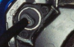
| Step 7 | Check to make sure that your new Yamaha socket fits the holes you made. It should be snug and the lip should be completely in the hole to prevent moisture and not fall out. Make sure you do this with the bulbs in, or you may make the hole too small. When you take it back out, make sure the bulb has not been pushed out of the socket, if so, try again. If it still gets pushed out, drill the hole out a bit more. Once you’re happy with the fit, remove the sockets, you’ll need to modify them later | |||||||||
  |
||||||||||
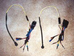
Wiring harness instructions |
||||||||||
| Step 1 | Make ground wires
|
|||||||||
 |
||||||||||
| Step 2 | Make signal wires
|
|||||||||
 |
||||||||||
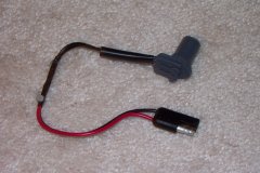
| Step 3 | Make relay connections
|
|||||||||
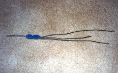
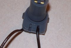
| Step 4 | Attach other trailer harness end to Yamaha socket
|
|||||||||
   |
||||||||||
| Step 5 | Repeat steps 1-4 for the other side | |||||||||
 |
||||||||||
Assembly |
||||||||||
| Step 1 | Re-install the headlight | |||||||||
| Step 2 | Install running light sockets in the headlight | |||||||||
 |
||||||||||
| Step 3 | Plug in the left and right front signal connections to the harness you had made | |||||||||
| Step 4 | Plug in the running light connectors to your harness | |||||||||
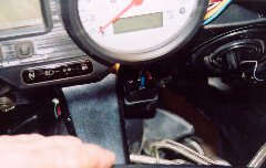
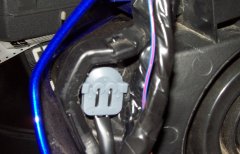
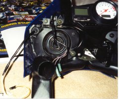
| Step 4a | Relay mount location on the Yamaha YZF-R6 | |||||||||
|
||||||||||
| Step 5 | Test to verify it works properly before riding | |||||||||
|
||||||||||
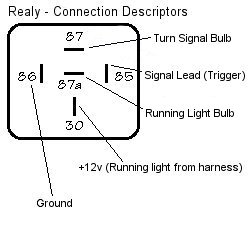
Diagrams |
||||||||||
 |
||||||||||
| Bottom view of relay | ||||||||||
 |
||||||||||
| Wiring diagram | ||||||||||
  |
||||||||||
| Relay Info | ||||||||||
|
|
|
 |
|
| FYI, This was the crap I had to deal with to create this mod, -12F (before wind chill), brrrrrrrr!!! | |